This page was archived in 2023 as part of the Mac Hut archive and is no longer updated.Most of the site pages were last updated around 2008 and some information may be out of date. Become a patron: Support our efforts by contributing a small amount each month to cover our hosting costs and the time it takes to archive these pages properly. Thank you. |
New, Detailed pictures are available. Click here
While creating my Takky Color Classic, I realized the fragility of Color Classic analog cards. This single board performs all the rectification of power for the entire computer, and it drives the high-voltage display, too. This board works hard while you're using your Color Classic. Performing the "Takky" modifications to your Color Classic only increase the stresses placed upon the board. Not only are the power requirements increased with the new motherboard, but the VGA-Mod or the Hi-Res mod will also increase stress on critical analog board components.
So, upgrading your Color Classic with the Takky mod greatly increases your chance of analog board failure, right? Here's the problem: Color Classic analog boards are terribly, horribly difficult to find a replacement for. I solved two problems with one mod by selling my original Color Classic analog board and fitting my Takky with one from a Macintosh LC575. Some collector got a nice replacement for his original-condition Mac, and I have an easy time finding replacement parts for my Mac that's already modded beyond the point of no return.
PLEASE do not perform this modification to a Color Classic that you're not also doing the Takky upgrade upon. These machines are getting rarer every day, and seeing one chopped up for lack of parts would be very saddening. Also, due to video timing differences, this modification will not work with a stock Color Classic analog board. The effect is as if the "Hi-Res" mod has already been performed. Proper adjustment of the monitor sense code lines would be required.
If, however, a Takky IS in your future, PLEASE perform this modification-you'll be happier and you'll also contribute to the preservation of another Color Classic somewhere else in the world by selling your original Analog Board.
This article will begin with a discussion of the physical and wiring modifications necessary to simply fit the 575 board into the Color Classic case, which will be followed by a discussion of further wiring concerns when this modification is performed at the same time as the "Takky" modification, as recommended. This modification will not work with a stock or "Mystic" upgraded Color Classic without modification of the monitor sense line coding, which I will not discuss.
Being that I live in a litigious country, I hasten to point out that this article is meant to be used only for scholarly purposes, and that while these procedures worked for me and my Takky, they may not work for you, that any risks involved are yours alone, that I will in no way be liable for any actions you may take or the consequences thereof, and that I do not recommend that you actually perform this modification to your own computer. Any decisions you make must be made on your own, dammit. I'm just trying to be helpful!
The LC575 Analog board is a lot wider than the entire Color Classic is, so we're going to have to cut it down to size. Unfortunately, the "infamous bump" is going to make the process a lot more difficult. Fortunately, the infamous bump is just barely narrow enough to fit inside the Color Classic case with about a millimeter of total room to spare.
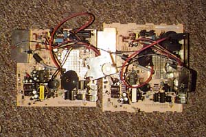
This is what you're up against. The board on the left is my failed board, already cut down to fit inside my Takky. The board on the right is stock. Look at how much wider it is! This won't be too big of a deal, though.
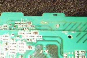
Remove the metal cover from the wiring harness connector and set it aside. You'll have to modify it later. First, you'll want to use an abrasive cutoff wheel in a Dremel tool to make a rough cut and remove most of the excess material. Cut to within a couple millimeters of the edge of the circuits. Here's a part of the board before any cutting is done, to show how much needs to be removed:
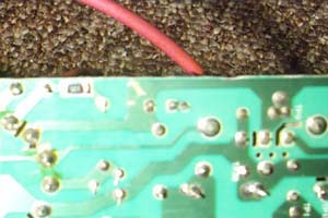
Now that you've got a rough cut made, you're going to have to slowly and carefully take off more and more material until you get the board to just extend beyond the widest circuit. Do this on both sides of the board, filing down the edges of the rough-cut board to within half a millimeter of the circuits. Using a hand file will make doing this carefully enough much easier. This is how close you'll need to come, on both sides:
Now that you've got the board narrow enough to fit inside the Color Classic case, you'll need to narrow the metal connector shield down to fit. Just bend and cut it with the dremel. Here's what mine looked like:
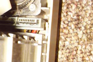
With the stock analog board, the cooling fan (mounted in the caseback) receives power by being properly spaced to make touch-contact with terminals on the back of the analog board. This new analog board throws off that spacing. To supply power to the case fan, cut off both a male and female drive power connector from a Y-cable. Leave about 3" of pigtail on both connectors, and remove both inside pins, leaving only two pins in the connectors. Tin and solder the "male" connector to the fan power contacts on the back of the analog board, observing polarity. Set the modified female connector aside for later use.
Even when the LC575 Analog board is cut down to its smallest size, it is still wider than the Color Classic analog board. In order to fit it inside, the plastic "frame" needs to be modified. Instead of sliding in to a "channel" in the plastic, the new analog board will sit on top of a "picket fence" of plastic points left over from cutting away the "channel". The tops of these points are at about the same level as the "channel" was, but without the extra width penalty (or the convenience of sliding parts).
Totally disassemble the Color Classic and remove the plastic inner frame. Using a dremel and an abrasive cutoff wheel, remove the twin plastic channels by cutting across the very top of the line of holes just beneath the channel. This will leave the "picket fence" that the new analog board will sit on.
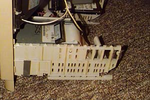
After the top of the frame is modified to allow the full width of the case to be used, the connector for the wiring harness needs to be moved about 1/2" to the right. This is due to the extra size of the new analog board.
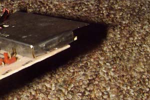
In order to accomplish this, simply cut away the frame area that holds the connector in place. It will also be necessary to cut away a bit from the top of the clip that holds the frame to the case front. This will prevent the clip from interfering with the connection of the connector to the board. The connector will just float freely in the case now, and will only be held in place by the friction of its connection to the analog board. This is what it looks like assembled.
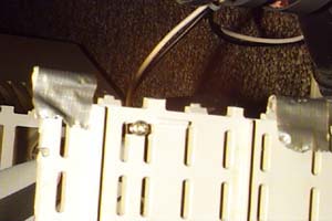
You might find, like I did, that after the cutting is all complete, the Analog Board doesn't sit quite level on top of the frame assembly. I solved this problem by shimming the frame assembly upward with rolled up little pieces of duct tape. I'm sure there is a more appropriate way, but this method has worked for me for a couple of years now. :-)
Finally, we must address case fan power. Unclip the case fan assembly from the caseback and use a screwdriver to disassemble it. Clip the wires that run from the fan to the contact assembly, and solder and connect them to the modified female drive power connector you set aside previously. Make sure to observe proper polarity, and reassemble the case fan assembly and reinsert it into the caseback.
Assemble the Color Classic casefront with button board, wiring harness, case front, and plastic frame as ususal. Next, place the modified Analog Board into its position and, using dexterous fingers, connect it with the wiring harness connector. Using a pencil or screwdriver as a lever might prove advantageous. Turn the Color Classic onto its front panel and slowly slide the caseback on. You'll see that the main power connector has moved slightly to the right. Remove the caseback and, using a flat file, file the power connector opening to fit. Also, if the caseback binds, check the edges of the analog board for straightness and file further for proper fitment.
Continue to hook the analog board up to the CRT in the usual manner. Once all connections are complete, turn the Color Classic onto its front panel and slowly slide the caseback onto the Color Classic. When the case is about halfway on, make sure to connect the case fan power connectors to supply power to the case fan. Finish sliding the caseback on, and button her up in the usual way. You're done! Now adjust the picture as you would for an LC575, and enjoy your upgrade.
This analog board comes from Apple configured to operate at 640x480 resolution with a 66Hz vertical refresh rate. The "Hi-Res" mod or "VGA Mod" are *not* required, and will probably kill your 575 board if attempted. However, the sense line coding issues are still the same as those involved in those modifications. Setting the monitor sense line code to "Hi-Res" will probably work, but I have not tested it. I set my monitor sense line to "VGA" which in MacOS 9.0.4 gives me several working resolution choices: 640x480x66Hz, 640x480x60Hz, 800x600x60Hz, and 800x600x56Hz. At a given resolution, using a lower horizontal refresh rate helps to "widen" the picture, so if you can't adjust your picture to take up the whole monitor width, try switching to a lower horizontal refresh. 800x600 is nice and usable, though the dot pitch is a little grainy.
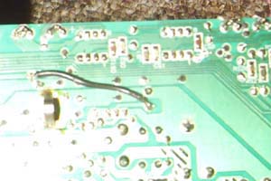
A very important part of the Takky modification is the modification of one of the Analog Board pins to provide -10 VDC instead of -5 VDC. This modification is very easy on the standard Color Classic analog board and I am happy to report that it is exactly the same for the LC575 Analog Board. The jumper that connects the output of the voltage regulator to the connector pin needs to be cut, and a jumper soldered in between the input of the voltage regulator and the connector pin trace. Here's what the backside of my board looks like after the voltage modification.
Text and Images copyright 2003-2008 Tyler Sable
Information is presented for research and enterntainment only
.
Any actions taken are the sole responsibility of the reader.
NO WARRANTY is expressed or implied.